
HOME / POSTS / MASS-MANUFACTURED NAUTICAL YO-YOS
Mass-Manufactured Nautical Yo-Yos
February 2017 Bianchini
My team of 5 people designed a nautical-themed yo-yo, which we designed for mass manufacturing and of which we fabricated 50. We learned how to design for manufacture, to use injection molding and thermoforming machines, and to use MasterCAM to program CNC mills and lathes. I specifically did the design, tooling manufacturing, and production run of the ship steering wheel featured on both sides of the yo-yo.
2.008 design and manufacturing 2
2.008 is the second Manufacturing + Design class for MIT mechanical engineers, and it focuses on mass manufacturing techniques and processes. The ongoing semester project was to manufacture 50+ yo-yos of custom design, using manufacturing techniques such as injection molding and thermoforming.
This video was one of our final deliverables at the end of our semester, and it shows my team's progress through the design and manufacturing.
Design

The yo-yo design in SolidWorks.
We made a nautical-themed yo-yo, each side featuring a ship steering wheel, compass arrows, and a textured panel designed to look like waves. Each yo-yo features the following parts:
| Part | Quantity |
Manufacturing Method |
| Body | 2 | Injection Molded |
| Steering Wheel | 2 | Injection Molded |
| Outer Ring | 2 | Injection Molded |
| Wave Pattern | 2 | Thermoformed |
| Hex Nuts | 2 | Off-the-shelf |
| Brass Nail | 2 | Off-the-shelf |
| Set Screw | 1 | Off-the-shelf |
| Axle Spacer | 1 | Off-the-shelf |
| String | 1 | Off-the-shelf |
Table 1: Yo-yo components, quantities, and manufacturing methods.
In addition to each of the components, we kept track of critical dimensions and tolerances, a tactic that is crucial in large scale production.
|
Critical Dimension |
Target Value |
Tolerances |
Measurement Method |
|
Overall yo-yo diameter |
2.52" |
+/-0.015" |
Calipers |
|
Overall yo-yo width |
1.485" |
+/-0.010" |
Calipers |
|
String gap |
0.1" |
+/-0.005" |
Calipers |
|
Body rim for snap fit (OD) |
2.2176” |
+0.005” -0.000” |
Micrometers |
|
Snapring rim for snap fit (ID) |
2.2076” |
+0.000” -0.005” |
Micrometers |
|
Waves thermoformed piece OD |
1.85” |
+/-0.010" |
Calipers |
|
Waves thermoformed piece ID |
0.5” |
+/-0.010" |
Calipers |
|
Steering wheel center hole diameter |
0.09” |
+0.005” -0.000” |
Calipers |
|
Steering wheel max OD |
1.785” |
+/-0.010” |
Calipers |
|
Steering wheel max thickness |
0.166 |
+/-0.015” |
Calipers |
|
Total mass |
0.07kg |
+/-.01kg |
Scale |
|
Max rotational speed |
197 rad/s |
+/-10 rad/s |
Logger pro |
Table 2: Critical dimensions for the yo-yo assembly/components.
Design for manufacturing
For injection-molded parts, common defects include shrinkage, flash, and short-shot. Shrinkage is the most difficult to alleviate, and it can be helped by maintaining a consistent thickness of the part throughout its shape. This led us to redesign one of our parts in order to combat some future problems down the road.

Compare the thickness through the red line from the original design (bottom) to the designed-for-manufacturing iteration (top). Injection molded parts with thick sections typically can show shrinkage marks because the outer edges harden before the molten inside, which then shrinks when it freezes.
Mold design for injection molding
Our yo-yo had three unique injection molded parts. I designed and manufactured the steering wheel, so I will go more into detail on that part. Because of the 3D-machined features, the part led itself to a symmetric split plane through the center of the part. Save for the central hole, all other features of the part were reflected symmetrically in either mold half (called the core and cavity molds). The central hole became a steel pin that was press-fit into the aluminum mold after its machining.

The mold halves for the steering wheel. They were CNC milled using operations made in MasterCAM software.
Mold manufacturing process plans
In large scale manufacturing, process plans are essential to predict time and money costs associated with manufacturing. We made a process plan for each of our manufactured tooling (e.g. molds for injection molding, molds for thermoforming).
|
Part |
Task |
Time Estimate |
Description |
|
Body |
Setup injection molding machine |
30 mins |
Put core and cavity mold in machine, learn how to operate controls |
|
Calibrate pressure and other parameters |
30 mins |
Make test pieces and adjust controls to make optimal parts |
|
|
Injection mold 100 bodies |
2 hours |
Put hardware in mold, close mold, inject plastic, let cool, release mold, repeat |
|
|
Body Molds |
Setup core and cavity on mill jig and run drill pattern on ProtoTrak for ejector pin holes. Then run gate mill program |
30 mins |
Load program onto mill, set z-zero, put in center drill, center drill holes, change to drill bit, drill holes, change to end mill, mill gates. |
|
Turn core on lathe |
10 mins setup 4 mins run (according to mastercam) |
Put rectangular stock in chuck, load program, verify program, run. |
|
|
Turn cavity on lathe |
10 mins setup 3 mins run (according to mastercam) |
Put rectangular stock in chuck, load program, verify program, run. |
|
|
Snap Ring |
Set up injection molding machine |
30 mins |
Put core and cavity mold in machine, learn how to operate controls |
|
Calibrate pressure and other parameters |
30 mins |
Make test pieces and adjust controls to make optimal parts |
|
|
Injection mold 100 snap rings |
1.5 hrs |
Put hardware in mold, close mold, inject plastic, let cool, release mold, repeat |
|
|
Snap Ring Molds |
Set up mill with rectangular stock |
10 min |
Put in stock, load program, run |
|
Machine cavity on mill |
50 minutes |
Set z-zero, face stock with 2” face mill, machine pocket with ½” end mill, machine around islands with 3/32” end mill |
|
|
Set up lathe with rectangular stock |
10 min |
Put in stock, load program, set zero |
|
|
Turn core on lathe |
3.5 mins |
Run core turning |
|
|
Set up mill with turned core |
10 mins |
Put in stock, load program, set zero |
|
|
Drill ejector pin holes on mill |
7 mins |
Machine series of 6 ejector pin holes, first with center drill then with pecking drill |
|
|
Wheel |
Setup injection molding machine |
30 mins |
Put core and cavity mold in machine, learn how to operate controls |
|
Calibrate pressure and other parameters |
30 mins |
Make test pieces and adjust controls to make optimal parts |
|
|
Injection mold 50 wheels |
2 hours |
Put hardware in mold, close mold, inject plastic, let cool, release mold, repeat |
|
|
Wheel Molds |
Setup core and cavity on mill jig and run the programs. |
Core: 1 hour 15 minutes Cavity: 5 hours 10 minutes |
Core: Load program onto mill, set z-zero, put on 2” facing bit, face mold, put in center drill, center drill holes, change to drill bit, drill holes, change to ½” end mill, mill top, change to 3/32” flat end mill, rough cut pockets, change to 1/16” flat end mill, finish cut pockets Cavity: Load program 1 onto mill, set z-zero, put on 2” facing bit, face mold, mill |
|
Waves |
Set up thermoforming machine with wave mold |
30 minutes |
Set up heating elements, insert plastic and position mold. |
|
Thermoform 100 wave pieces |
2 hours |
Heat plastic sheets, vacuum press mold, cool, remove sheet, repeat |
|
|
Punch out exterior and interior circles |
2 hours |
Individually cut out the outer diameter and interior through hole of the cooled sheets |
|
|
Wave Mold |
Set up 3D model in printing software, print |
4 hours |
Construct the mold using additive manufacturing methods. Cure if necessary. |
|
|
Total Time: |
19 hours + 45 min |
|
Table 3: Time estimates for manufacturing each of our custom parts, including their tooling.
Our timing assumptions for the machining of the molds came from the development of MasterCAM files for each part and determining the run time based off MasterCAM’s estimates. We took our injection molding estimates based on discussed standard setup times, giving ourselves some slack to calibrate the machine, and then standard injection and cooling times--making sure to account for larger cooling times for thicker parts.
Injection molding process optimization
Injection molding machines carefully control temperature and pressure with respect to time, and these profiles greatly vary the outcome of the parts. Before doing the production run, we made practice parts as we optimized the temperature/pressure profiles to achieve minimal defects and maximal quality. Those parameters for the body piece, as an example, are as follows:
~~~Injection Hold~~~
Injection Hold Pressure Profile:  P7-P16 = 500, 300, 300, 300, 300, 300, 300, 300, 300, 300
Injection Hold Time:  Z2 = 8.00s
Cooling Time:  Z4 = 10.00s
Set Screw Feed Stroke (shot size):  C1 = 2.20in

~~~Injection Boost~~~
Injection Speed Profile:  V12-V21 = 3.0, 3.5, 4.0, 3.0, 2.0, 1.0, 0.8, 0.4, 0.2, 0.1
Injection Boost Pressure:  P6 = 1700psi

~~~Screw Feeding~~~
Screw Feed Delay Time:  Z3 = 3.0s

~~~Ejector~~~
Ejector Counter:  2
⅛” Ejector Pins Length:  5.57in, Quantity:  6
Total Shim Thickness:  0.00in
¼” Ejector Pin Number:  #2
We arrived at these values with a couple of things in mind that we wanted to improve: dishing and rate. There also was a consistent visible weld line/air bubble across all our test parts, however this spot was going to be covered after assembling with the snap ring. Thus, we decided to not worry about this flaw.
To fix dishing, we considered changing the pressure profile so that it would pack in more material while cooling, hopefully filling in some of the dished areas. This resulted in our pressure profile holding 300 psi for the duration of the holding time.
To improve the rate, we considered decreasing the cooling time, at the potential expense of dimensional accuracy since the part shrinks more when it cools for longer outside of the mold. Thus, we decreased the cooling time and checked the dimensions to ensure the variations were still within specifications. This resulted in our decreasing the cooling time from 20 seconds to 10 seconds, which still allowed us to keep our parts within our design specifications.
We began with generic numbers based on our knowledgable shop staff. We tweaked the numbers as we went by tracking the defects in each of the practice parts like below.

We kept track of what parameters for injection molding worked best by noting which practice parts were most successful.
This is an example of a practice run that was a part of the process optimization process.
Production run injection molding


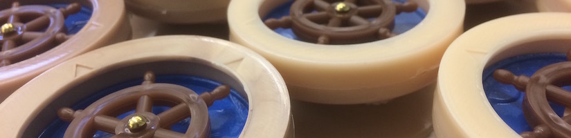
The outcome of the production runs of the body pieces (left) and steering wheels (right). We mixed different shades of brown into each of the parts to yield somewhat of a wood grain in each.

Note the color variations in the injection molded steering wheels: an intended result that we used to mimic wood.
Assembly

Our completed yo-yos!
Cost analysis

Injection molding and thermoforming are processes that are expensive in upfront time and money costs, making them unappealing for small scale production runs. However, the linear costs that increase with each part made are less significant, making those process more and more attractive at higher production run sizes.
Certain manufacturing methods do not make much sense at low quantities, such as the injection molding process used for the majority of our yo-yo parts. This is evident by the high estimated cost of $64.93 per yoyo at our manufactured 50 yo-yos, versus a much lower predicted cost of $8.17 per yoyo at 50,000 yo-yos. This significant price drop per unit is characteristic of manufacturing methods with high fixed costs, which get distributed among all units made in cost analysis.
In determining our cost of manufacture per yoyo, we considered many aspects of the manufacturing process, including cost of tooling, part materials, design labor, machining/programming time, machine run time, and overhead. Of those, we determined that the fixed costs that would be the same for quantities of 50 yo-yos and 50,000 yo-yos were the following:
- 3 pairs of mold blanks: we would not require more molds to make more parts, just more use of the same molds.
- 1 thermoform blank: same reasoning as the mold blanks.
- 4 shoulder bolts to make shafts to support nuts in molds: 4 of these bolts since they can be reused and are not consumed in the injection molding process for the body pieces.
- design labor: all of the designs don’t change no matter the quantity we manufacture, so increasing the parts would not demand more design time.
- machining and programming time: same reason as for design labor--the machines just have to be programmed once, so increasing the parts would not demand more programming time.
- instruction and overhead: the overhead for our instruction time would stay the same because increasing the parts would not demand more instruction.
Similarly, we determined that the variable costs, or costs that scale with the number of parts manufactured, were the following:
- plastic pellets for injection molding: each part needs its own share of the resin, so adding additional parts would increase this demand proportionally.
- thermoform material: every thermoformed part is made out of the thermoform material, so more part demand means higher material demand.
- hex nuts, 10-24 set screws, axle spacers, string: each yoyo consumes two hex nuts, one set screw, one axle spacer, and one string. Thus increasing the number of yoyos increases the demand for these parts linearly.
- injection molding run time: each injection molded part has its own cycle time, so the run time would scale up linearly with parts made, and therefore so would the cost.
- thermoforming run time: for the same reason as injection molding run time.
This took a lot of math to quantify precisely, but the tl;dr is that injection molding is not very viable to do (cost-effectively) if you're going to make under 1000 parts.