
HOME / POSTS / SPACE TACO CORGI: MECHATRONIC ROBOT
Space Taco Corgi: Mechatronic Robot
February 2019 Bianchini
For the notorious Stanford mechatronics course project, 3 of my classmates and I constructed a robot designed to play the 2019 ME218B challenge: the Great Pacific Garbage Patch. Designed to compete in 1-on-1 matches, autonomous robots were designed to commence when they received a start game signal, collect "garbage" (foam balls) throughout the game field, try to recycle as many as they could based on the garbage color, then throw the rest away into a landfill. All actions were autonomous, including localization, given that the robots were started in a random configuration every match.
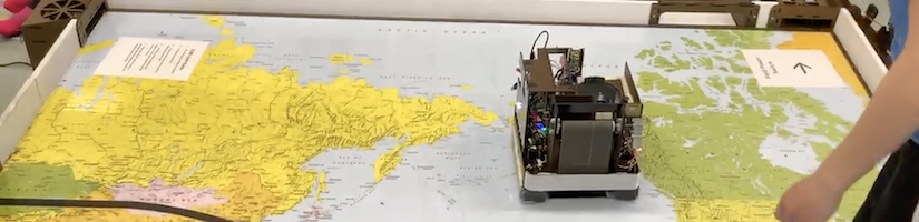
Video 1: A brief overview and demonstration of our robot and its sub-systems.
Overview
My team and I designed all parts of this system, whose brain was a Tiva LaunchPad, which we programmed in C. We soldered all of our circuits to protoboards to balance robustness with speed of development, and we designed and built all mechanical hardware from scratch as well. We were the top-scoring team during the project check-off session, during which we scored in both the landfill and recycling center. My teammates and I went a little overboard with decorative LEDs in between the check-off session and the actual competition, so our robot drew too much current and fried during the competition.

Figure 1: The Space Taco Corgi team.
Note: Our final deliverable for the class project was in the form of a website, which you can check out here. In contrast to that site's low-level details, this post contains a high-level overview of what we made, with some of the interesting details highlighted. This project was an extremely collaborative process, and my teammates and I tackled nearly all problems together.
Game rules
Historically, the documents outlining ME218 game rules are known for their humor, so I attached the pdf file to this post. Generally, game play goes as follows. Designed to compete in 1-on-1 matches, autonomous robots must commence when they receive a start game signal, collect "garbage" (foam balls) throughout the game field, sort the garbage into recyclables or trash (based on ball color), recycle what they can then throw the rest away into a landfill, all while displaying their team designation and detecting collisions. All actions are autonomous, including localization, given that the robots start in a random configuration every match.

FIgure 2: The game field, featuring a map of the Pacific ocean, 2 landfills, 2 recycling centers, a black tape leading between the recycling centers, and 4 fans to blow the garbage pieces in a swirling fashion.
Systems-level concepts
Our first brainstorming focus was on the mechanical design. We separated into sub-systems: ball collection, ball sorting, and ball storage.
Ball collection

Figure 3: My first concept of our ball collection mechanism.
We ended up pursuing my first sketched ball collection concept: a conveyer belt mechanism. We bought small belts for a belt sander and used that as the belt. To control the tension, we added slots in the upper roller (PVC pipe) mounting point so we could adjust how tight or loose the belt was.
Ball sorting

Figure 4: My first concept of how to sort the collected balls.
In order to pursue recycling and get the big points, we needed to be able to differentiate between recyclable and non-recyclable balls. Teams were provided with color sensors, a TCS34725. The idea for sorting the balls was to funnel our collected balls into a spot where the color sensor would determine which location a stepper motor would feed the ball into: recyclables or trash. Each of those two shoots would lead to a small storage area where the robot would keep those balls, then from which they could get released later all at once.
The only change we made from my original design to our implemented robot was using a servo motor instead of a stepper motor. Since we used a non-continuous servo, this meant our rotating disk would twist to drop the ball into the designated shoot, then twist back to accept the next ball (a change from the stepper motor design). Using a servo was simpler to implement on the electrical control side, and the servo itself was much smaller than the steppers we had available. Turns out we didn't need the continuous capabilities of the stepper based on how many balls we were collecting at once (less than anticipated), so this was a clear change for us to make.
Ball storage

Figure 5: Ball collection, sorting, and storage layout.
We wanted space for us to store both some recyclables and some trash balls, plus it would be good to have space for additional unsorted ball storage in case we keep collecting beyond our sorted storage allocations. We nixed the expandable net idea, as we reached the limits of our sorted storage well into the match, not problematically early.
A couple of considerations determined this specific layout of our storage. Firstly, we wanted to be able to both collect and dispense on sides of the robot that were directions it could move, i.e. the front and/or back of the robot as opposed to the right/left sides. This way, we could easily collect balls we ran into, as well as we could directly approach the drop-off locations. Secondly, the recyclables could only be deposited on ground-level, whereas the trash could be deposited either on ground-level or from above. Thus, we designed our recyclables shoot to let out the recyclable balls on ground level, below the bumper, while the trash balls were released above the bumper.
Localization
There are infrared (IR) beacons at each of the two landfills and two recycling centers to assist the robots in determining where on the field they are located. Each of those four beacons emits pulses of IR light at different frequencies, so the robots could figure out which direction they are facing by measuring the IR pulsing frequencies when they detect a signal. Other features to help with localization were a black tape line through the middle of the field, under which there was a wire carrying a 100 mA current modulated at a frequency of 20 kHz, which could be detected using a hall effect sensor.

Figure 6: Aerial layout of robot orientation, sensors, collection system, and dispensing system, including beacon sensors and directions.
My team decided to make use of the black tape and IR beacons. To keep the system simple, we decided early that our robot would spend the first part of each match largely blindly collecting garbage, not paying attention to where it was on the field. Once we either filled up our sorted ball storage or the match was coming to an end, we would determine where on the field the robot was. Thus, we put a beacon sensor on the rear of the robot, which is the dispensing side. We added a beacon sensor on the right side as well so this would help with our algorithm for lining up with the recycling centers better (look for the state diagrams later in this post).
Object detection + drivetrain


Figures 7: Aerial view of our bumper concept with limit switches (left), and an isometric view of a simplistic view of the whole system (right).
We needed to detect if our robot ran into obstacles, whether the opponent robot or the game field walls. We decided to be able to detect if we hit objects on the front or back of our robot, since only our opponent robot would be able to cause a sideways collision, and we were depending on our opponents to be able to detect the collision to get out of that situation. A limit switch in each corner, each facing either forwards or backwards, would toggle when our bumper deformed. This bumper would sit in front of all other parts of the robot for meeting the safety requirements.
We kept our drivetrain simple: we used the two motors provided to our team for the project, and we kept them centered in the chassis. To keep the robot balanced, we designed and 3D printed smooth pegs for each of the robot's 4 corners. These pegs were slightly short of the floor, to ensure the wheels would contact the playing field. This meant the robot would tip slightly as it transferred weight from the front set of pegs to the back set after pivoting over the wheels, but this wasn't noticeable given the small height difference we incorporated.
Mechanical design + implementation
Everything had to fit into a pretty tight package: a 1-foot cube. The majority of the structure was made out of duron, a hard board made of wood fibers without adhesives. I had never seen this material during my time at MIT, but it's the most commonly laser cut material on Stanford campus and worked well for our application.
Drivetrain

Figure 8: CAD of the drive train and bottom layer of the robot.
The bottom layer of the robot featured custom aluminum motor mounts. The motors were coupled to a wheel shaft using a compliant shaft coupler to assist with any mechanical misalignments. The wheel shafts were supported on both sides by vertically mounted bearings. Circuit boards for the motor drivers were located on this layer too for convenience near the motors. The system batteries were fixed to the bottom of the layer's duron board, allowing for easy replacement. This CAD screenshot also shows the limit switches for the bumper, described in more detail below.
Bumper

Figure 9: CAD screenshot of an isolated bumper system.
We used compression springs to keep the bumpers biased outwards so it did not toggle the limit switches until contacted by a force above an experimentally-determined threshold. We could adjust this by tightening/loosening a bolt that goes through the center of the compression spring.

Figure 10: CAD screenshot of the second tier of the robot, encompassed by the bumper.
The second tier of the robot was held to the first by standoffs. This second tier is wrapped entirely by the bumpers and features our power distribution board.
Collection system

Figure 11: CAD screenshots of the conveyor belt ball collection system.
The balls were collected with a conveyor belt made out of a couple belt sander belts. We made the conveyor belt as wide as we could fit within our small robot footprint so that we could maximize the chance that we would blindly pick up a ball. Any balls drawn up the conveyor belt were funneled so that the top of the conveyor belt let out a single-file stream of balls. We selected a high-torque, low-speed motor for driving this conveyor belt. The rollers for the conveyor belt were made out of simple PVC pipe. We could adjust the tension in the belt by incorporating slots for the roller's shaft bearing mounts in the duron supports. We designed and 3D printed a scoop that would draw the balls into the belt shaft.

Figure 12: Drawing that led to our solution to the pressure problem on the collected balls.
We didn't initially have a plate in the middle of the belt. Experimentation showed that we couldn't tension the conveyor belt tightly enough to apply enough pressure at the center of its length, so we added a plate that was surrounded by the belt itself. When the collecting balls applied pressure on the belt, the belt was supported by this plate, which rubs against the smooth back of the belt. This worked quite well.
Sorting and dispensing system

Figure 13: CAD screenshot of the sorting and dispensing systems.
Once the conveyor belt let out a single-file stream of balls, one ball at a time would drop into our sorting disk's opening. This opening lined the ball up with the color sensor right below the top layer. Once the color sensor determined what color the ball was, the robot would decide if that color was recyclable or not based on the packet of data that outlined the current game rules. This decision would determine if the sorting disk's servo dropped the ball into the recyclable (a clockwise twist) or trash (a counter-clockwise twist) shoots. Each of those shoots retained the contained balls using another servo with an arm that could retain then release them on queue.
Electrical component storage


Figures 14: CAD screenshots expose some of the circuits, including the tape sensor circuits, the IR detection circuits, the IR emitter circuits, and the Tiva LaunchPad, the Tiva pinout distribution board, and the COMPASS.
In addition to the motor controllers on the lowest level near the motors and the second tier power distribution boards, we stored many of our circuits on layers of vertical walls next to the ball dispensing system.
The two small circuit boards that remain exposed in the rightmost image are the IR detection circuits. The aforementioned COMPASS was a component provided by the class to each team. In reality, it is just an XBee for wireless communication. Our Tiva could query the COMPASS, which would provide information about the game such as team assignments, game start/end notifications, which colors were recyclable for each team, and which frequency was used as each team's code to unlock the recycling centers.
Full system

Figure 15: Dimensions of the robot in inches -- all under 12". This view shows the front and left sides of the robot, which boast the large conveyor belt for collecting garbage.

Figure 16: The back side of the robot shows the sorting system as well as the 2 dispensing systems.
Electrical design
Figure 17: Schematics for all circuits in the project.
The electrical designs were not too complicated, for the most part. Here is a list of the electrical components we used:
- 2 drive motors
- 2 encoders for drive motors
- 2 H-bridge motor drivers for the drive motors
- 2 custom IR detector circuits
- 1 5V buck converter
- 1 color sensor
- 1 "COMPASS", which was a communication device provided to teams by the teaching team (the inside of it was a PIC microcontroller and an XBee)
- 1 custom tape sensor circuit
- 1 motor for the conveyor belt
- 1 H-bridge circuit for the conveyor motor
- 4 limit switches for the bumpers
- 1 IR emitter circuit for opening the recycling center
- 1 servo for sorting the foam balls
- 2 servos for releasing balls from the recycling and landfill storage compartments
- 1 servo for raising team flag indicator
The most complicated circuit we built and tuned were the IR detection circuits. This circuit detected IR light from a phototransistor, which was amplified through two gain stages, filtered through a high pass filter to eliminate any steady-state IR light from the sun, then passed through a Schmidt trigger to digitize the signal. We connected this signal to an interrupt-capable pin on the Tiva, since the different frequencies emitted by the different beacons were close enough together that timing precision mattered to differentiate them.
Software
Figure 18: State diagrams for our software.
Above you can find the state diagrams we made to first design the structure of our software. With these as guidance, we wrote the code files attached as a zip file to this post.