
HOME / POSTS / BASEBALL MUSIC BOX
Baseball Music Box
October 2018 Bianchini
I wanted to build a unique engineering-focused display for a baseball in a way that would make people laugh. I used this idea for my project in Stanford's class ME203 Design and Manufacturing. My inspiration came from my desire to make a gift for a family friend whose was a Major League baseball player when he was younger, then became an engineer for the rest of his career. Thus, a baseball display with exposed engineering elements would be the perfect way for my friend to display a piece of his young and later life in her apartment.
Motivation + opportunity
I knew I wanted to make something for this friend of mine for a while. She was one of the key people in getting me interested and involved in engineering at an early age, so engineering something for her made a lot of sense.

Figure 1: The first sketch I made of this project idea.
During my first quarter at Stanford, I took ME203 Design and Manufacturing, one of the cornerstone Product Realization Lab (PRL) classes. Stanford does machine shops differently than MIT, which has dozens of separate shops with different equipment for different purposes and available to different subgroups of people. Stanford has the PRL, which is one expansive, all-inclusive machine shop for any university affiliates to use. It's pretty impressive, including a casting foundry, welding equipment, forming tools, mills, lathes, CNC mills, CNC lathes, a finishing lab, rapid prototyping tools, and a fully-stocked wood shop. You can find all of this at MIT, too, just scattered around campus and not always accessible to everyone.
Initial prototype
As a proof-of-concept, I built my first prototype out of Lego Mindstorms. Though this prototype did not resemble the form I desired for the final product, it had all of the design features incorporated, including the hand-powered crank, rolling the baseball, and playing the music from the music box.
Video 1: First assembly of Lego Mindstorms prototype.
Video 2: Including a hand crank on the Lego Mindstorms prototype.
Video 3: The final Lego Mindstorms prototype could roll a baseball in place and play "Take Me out to the Ball Game," all powered by a hand crank.
This prototype helped me see how likely it would be that I could have the front roller be passive, as in it would only rotate when pushed by the friction against it and the ball. This worked quite well for this prototype, so I included this in my final design.
Design

Figure 2: CAD assembly.

Figure 3: Sketch to help determine the length of the rear shaft.


Figures 4 + 5: Sketches to help determine the length of the front and bottom shafts.
Features
The music box is mainly composed of a gearbox. This gearbox is powered by the user via a hand crank. This rotary motion turns the rear rollers, which makes a baseball sitting on it start to roll. This baseball’s motion makes the front roller turn as well; otherwise, this front roller is passive. The rear shaft is coupled to the lower shaft via gears. This lower shaft is coupled to the hand crank of the purchased music box. Thus, the user’s hand cranking motion makes the ball roll and the music box play.
Design details

Figure 6: Sketch of an early design's exploded assembly.
I made Patti’s game with three aluminum plates: bottom, right, and left plates.

Figure 7: Three aluminum plates comprise the gearbox structure.
There are two shafts that run across both the right and left plates, and these shafts have wooden rollers pressed onto them that make contact with the ball. The shafts are held in alignment with brass bushings that are press fit into the right and left plates.
The o-rings on the wooden rollers ensure high enough friction contact with the ball such that it successfully rolls and can get the passive front roller moving. The music box is mounted on top of the bottom plate. This component had three tapped holes in its base already, so I matched the hole pattern and conveniently mounted the music box.

Figure 8: The music box is mounted directly to the bottom plate easily because of its already incorporated three tapped holes.
The coupler piece was the most interesting component in terms of design. It remains fixed on the lower shaft with a set screw, then its geometry “grabs” the handle of the music box and spins it. I left the size of the coupler to be minimal so one can see how it interfaces with the music box’s built-in handle. This method was non-invasive to the music box, so I could even swap out the music box for different songs if desired.

Figure 9: An early sketch of the design of the music coupler.
Video 4: The coupler piece fits nicely with the music box handle.
The gears are purchased, as is the spinning handle piece. I fabricated the wheel component of the hand crank out of aluminum rod. It stays on the shaft by using a set screw, and it connects to the purchased spinning handle piece by incorporating a tapped hole into which the fixed threaded stud to screws.
I made the wooden rollers by turning them on the wood lathe. I used the pen making tools to fixture the wood in place after putting a hole through the center of them (which turned out to be the most difficult step). I put small grooves in the rollers so the o-rings would stay in place.

Figure 10: Turning the second roller to match the first.

Figure 11: Both finished rollers with O-rings installed. The O-rings sit in turned grooves in the wood.
After rounding the corners of the bottom plate, I was able to rout out a pocket into my wood block such that the bottom plate could be pressed into the wood and be recessed. I chamfered the upper wooden base edges using a routing table.

Figure 12: I rounded some corners of my rectangular aluminum pieces using a Prototrak mill.

Figure 13: After rounding the corners of the bottom plate, I routed a pocket into my wooden base so that the aluminum plate could be recessed into the wooden component.
For finishes, I oiled my wood pieces, and I sanded and anodized my aluminum pieces in clear.

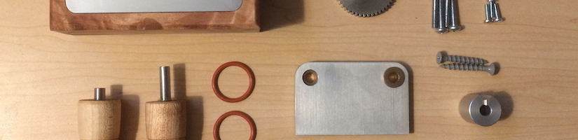
Figure 14: All of the components that go into the final assembly.
Challenges during manufacturing
The three most difficult aspects of the manufacturing process were eliminating slip between the baseball and the wooden rollers, aligning the shafts such that they both spin freely, and drilling holes through the center of the rollers.
Slip between ball and rollers
My original design had bare wooden rollers without o-rings. When the assembly was new, the baseball always rolled nicely on the rollers. However, with use, the wooden rollers must have gotten smoother, for the baseball began to commonly slip on the bare wooden rollers. I brainstormed a variety of different solutions to this problem, and I ended up deciding to incorporate rubber o-rings into the design. This fixed the problem right away, and I believe it did not detract from the aesthetic design.
Video 5: The first several times testing the assembly showed that the baseball could successfully grip onto the wooden rollers.
Video 6: After some use, the baseball began slipping on the bare wooden rollers.

Figure 15: Sketches of possible remediations to eliminate the slip between the baseball and roller.
Video 7: Incorporating the rubber o-rings on even just the front roller immediately fixed the slipping problem. I later incorporated the o-rings into both rollers for symmetry as well as for preventing further slipping that might otherwise arise with the rear roller.
Aligning the shafts
For aligning the shafts, in retrospect, I should have machined the side plates together so that I was confident the hole alignments were as exact as they could get. I am not totally confident this would guarantee alignment of the bushings since there could be imprecisions in the bushings themselves or in pressing the bushings into the plate holes. However, I do know for certain that machining the right and left plates separately, as I did, was not sufficient for alignment purposes. I had to re-ream through the bushings after they were pressed into the plate holes in order to get the shafts to spin well. Even after doing this step, assembling the gearbox took a lot of patience and care, for the 1⁄4” thick plates are thin enough to be able to be tightened over a wide enough range of angles that can make the shafts bind. Since I am not expecting to have to disassemble the gearbox often, I am okay with this outcome and decided against incorporating features that would help make this alignment more repeatable and lower effort.
Video 8: The assembled gearbox. Getting the shafts to rotate this smoothly takes a lot of time and patience -- though it won't have to be redone after final assembly.
Drilling holes through the center of the rollers
For drilling the holes through the center of the rollers, I luckily bought way too much wooden dowel than I needed, so I could practice making holes. I wanted to drill the hole first, then turn the wood on the wood lathe with reference to the central axis defined by the drilled hole. Thus, the drilled hole didn’t have to be perfectly centered since I would turn the rod with respect to it afterwards. I first tried drilling the holes using the drill press. The holes need to be drilled through the hole length of the roller plus some extra thickness on either side, extending to about 3.5”. By the time the drill bit went through the first end on center, the bit could flex and travel off-center significantly before reaching the other end. The first two hole attempts were so far off center that I would not have enough wood thickness around the hole to achieve the overall diameter I wanted. I later found jaws for the wood lathe that could grip (questionably) sufficiently onto the long spindle-like dowel pieces, so I tried this method and used the tailstock to drill the hole. This method produced much straighter and more aligned holes. Then I held those dowels with the holes through their center using the pen making fixture for the wood lathe.

Figure 16: My first three attempts (numbered in sequential order) at drilling a hole straight through a 3.5" long wooden dowel. I clearly made progress.
Final results

Figure 17: The final product!


Figures 18-20: Front and side views.

Figure 21: The final product can work with any baseball.