
HOME / POSTS / SIMPLE CLOCK PCBS
Simple Clock PCBs
January 2020 Bianchini-Love
Project Documents
After completing our Simple Clock project, which housed four breadboards full of clock components, we decided to make a PCB version. This version has all of the same components and capabilities of Simple Clock, all in a much smaller form factor that we designed to comfortably sit on a surface.
Overview
This clock is very similar to the breadboarded Simple Clock project, which has nearly identical circuitry and firmware. The PCB version of this clock is meant to sit on a desk or a shelf, though may be mounted in other ways using the threaded insert that protrudes from the back of the PCB. The clock provides two different brightness modes: manual brightness and auto brightness. In manual brightness mode, the brightness of the display is adjusted using a potentiometer, and will remain at that brightness until adjusted by the user. In auto brightness mode, the brightness of the display will change depending on the ambient light in the environment. In this mode, the potentiometer should be set to approximately 8 o'clock. Time is set using a single push button, which when held, will speed up the clock. If the set button is held for a prolonged period of time, the clock will increment even faster. When the desired time is displayed, the set time button may be released, and the clock will resume keeping time at a normal pace.

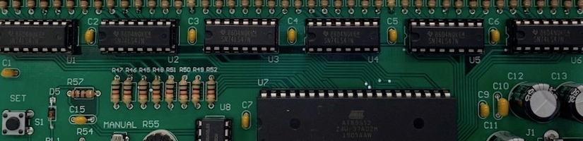
Figure 1: Simple Clock PCB
Construction
Since we already had a baseline schematic for this clock from our Simple Clock project, getting our PCBs made involved making minor schematic adjustments and laying out the components. Construction involved a lot of soldering, but the results were worth it. You can find the gerber files for the PCB under "Project Documents" as SIMPLE_CLOCK.zip.

Figure 2: The top layer of the PCB.

Figure 3: The bottom layer of the PCB.

Figure 4: We first soldered the threaded inserts to the PCBs, seen here as the circle of solder (the underside of the threaded insert).

Figure 5: Close-up shot of the solder for the threaded insert. As you can see by the print screen, the microcontroller socket fits neatly over the insert, so this circle of solder is never seen again.

Figure 6: Soldering.

Figure 7: More soldering...

Figure 8: A completed Simple Clock PCB!
User interface
The clock has a minimal and simple user interface. These feature are reiterated in the attached Simple Clock Manual, which can be found under "Project Documents" on this page.
Power plug
Use the plug on the lower right corner of the PCB (looking at the PCB from the front) to provide power to the clock. The power supply is rated for 5V (DC) at 2A.
Time set button
Use the "SET" button to set the time of the clock. Holding down this button increases the clock speed; a prolonged press increases the speed even more.
Dimming mode switch
Toggle the switch on the PCB to have the display brightness be set automatically or manually. Note: point the display dimmer at ~8 o'clock when in "AUTO" mode.
Display dimmer
Use this potentiometer to change the display brightness in "MANUAL" mode. Note: point the display dimmer at ~8 o'clock when in "AUTO" mode.
Clock angle
We brainstormed a variety of ways for the clock to sit in a stable position on its own. We selected one of the simplest methods, which involved soldering a threaded insert to the PCB, neatly tucked under the microcontroller. Then a bolt can be threaded into the back of the PCB and act as a third leg.

Figure 9: A brainstorming session for how the clock could sit on its own.

Figure 10: Sketches of measurements for sizing the bolt options so we could get a desired tilt angle.

Figure 11: We used Onshape, a handy CAD software, to calculate bolt lengths given our PCB geometry and a desired tilt angle.
Choose 1 of the 3 provided bolts and rubber caps to position the clock at a desired viewing angle. Install the bolt in the threaded insert on the back of the PCB.
| Bolt Length | Tilt angle from vertical |
| Short | 25° |
| Medium | 18° |
| Long | 12° |
Table 1: Bolt lengths and corresponding viewing angles.
Calibration
With each clock being slightly different due to component tolerances, each and every clock has been calibrated to minimize drift. During calibration, each clock was run over a period of a week and compared to a reference clock. The amount of seconds lost or gained over the course of one week was recorded and the corresponding correction was made to each clock in firmware.

Figure 12: A surge protector with a switch allowed us to start all of the clocks at the same time. This let us perform controlled experiments to help us with calibration.

Figure 13: Over the course of our one week (actually 6 days 23 hours) experiment, we logged how many seconds each of the clocks was slow.


Figure 14: Experiment 1. All clocks started at midnight on a Saturday night (top), compared next to a reference clock. 6 days and 23 hours later (bottom), the clocks display significant drift (~15 seconds) from the reference clock, and some drift among each other (~4 seconds).


Figure 15: Experiment 2. After implementing a software correction for the drift of the clocks, the second experiment showed no discernible drift from the reference clock or among each other over the course of another 6 day 23 hour period. Left is the start image, and right is the ending image.
We have included a copy of our assembly and hex code under "Project Documents" as SIMPLE_CLOCK_PCB.asm and SIMPLE_CLOCK_PCB.hex respectively. Note that this file implements software-corrected timing for the average of all the clock units we have built. Thus, this might not be exact for each specific clock, and there is a calibration number in there that might have to be re-adjusted depending on any specific hardware. There are some comments in the code that explain some possible values, including which specific clocks we have made and which values they were given. This average value would be a good start at mitigating some of the drift we've observed.
Easter egg
You've made it this far in the post, so you should know about the built in Easter egg! Plugging in the clock while simultaneously holding down the "SET" button will launch the clock into a hidden mode. To exit this mode, hold down the "SET" button for an extended period, and the clock will resume normal operation. If you go hunting in our SIMPLE_CLOCK_PCB.asm file, you might even figure out the behavior :)