
HOME / POSTS / SIMPLE CLOCK
Simple Clock
September 2019 Bianchini-Love
Simple clock is a just as the name implies: a minimalistic clock that has one button and one potentiometer and no extraneous features. The button is used to set the time; pressing and holding the button speeds up the seconds by a factor of 250 and a prolonged press of the button (after pressing the button for roughly 6 seconds real time) puts the clock into super fast mode, with one hour ticking by approximately every second. The potentiometer controls the brightness of the entire display, including the colons. This project uses the display and part of the code from Henry's final project from 6.115 - Microcomputer Project Laboratory. After re-discovering the breadboarded 7-segments displays, the project was resurrected and behold SIMPLE CLOCK!!!!

Figure 1: Close-up of Simple Clock in the shadow box frame.
Overview
The brain of Simple Clock is an AT89S52, a microcontroller that is compatible with the Intel MCS-51 family. The benefit of using this microcontroller is that it can be programed in circuit using an Arduino; no need for a specialty programming device. This was extremely useful for development purposes. To keep time, the AT89S52 uses a 12MHz crystal which is subdivided inside the microcontroller. Hours, minutes, and seconds are displayed on large, one inch 7-segment LED displays that are easy to read from any angle. The clock lives up to its name; there are no alarms, or extraneous features; it is purely a time keeping device, with only 12hour mode available and no AM/PM indication. The simplicity was desired and made it possible to complete the clock (note the that the 7-segment LEDs and their respective drivers were already wired) in one day.

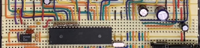
Figure 2: The electronics of Simple Clock.
Schematic
Simple Clock schematic (also available under "Project Documents").
Display
There is nothing fancy about the hardware of the clock. Every display is directly driven using a BCD to 7-segment decoder for each display. Four, red LEDs form the colon, which are consistently on and do not flash. Directly driven displays allow for maximal brightness and make it easy to use PWM to dim all displays evenly. If multiplexing were used, the timing of the PWM for dimming would be more critical for proper operation, and full brightness would not be an option. The data point (dp) of the 7-segment displays are unused, and there is no blanking of leading zeros; that is, 3:11:00 is actually displayed as 03:11:00.
PWM
To create the PWM used to dim all the displays, a 555 timer was used. In this simple circuit, the potentiometer adjusts the duty cycle of the PWM waveform from ~0% to 100%. The PWM feeds into the blanking input of all the BCD to 7-segment display decoders and is additionally used to power the 4 colon LEDs.
Video 1: You can watch the dimming functionality of Simple Clock in the dark.
MCU
As stated above, the AT89S52 was used as the microcontroller and "brain" of Simple Clock. A 12MHz crystal is used as the MCU clock, which is specifically chosen such that one machine cycle is exactly 1us. This creates a timebase such that one million machine cycles equals one second.

Figure 3: If the crystal oscillator is 12MHz, the timer is incremented every machine cycle, or equivalently, every 1us.
Port 0 requires 8 pull-up resistors as they are not internally provided (at least by default) by the AT89S52 (it's possible port 0 can be configured to have internal pull-ups, however, it was easier to just add them externally). A simple capacitor and resistor form a reset on power-up circuit that automatically resets the microcontroller when power is applied. The reset/default time is 12:00:00. A momentary push button switch is used on port 1. This button is the button used to set the time of the clock, and in software, P1.1 is configured as an input, while P1.0 and P1.2 are written high and low, respectively. This clever setup does not require any additional breadboard wiring or pull-up/pull-down resistors! Finally, P0, P2, and P3 are all wired to the BCD to 7-segment decoders. P3 handles the seconds, P2, handles the minutes, and P0 handles the hours.
Power
Power is supplied to the clock via a 5V wall-wart. This eliminates the need for any linear regulators or high voltage on the breadboard. The bypass caps are a suggestion and more or less can be added/subtracted based on the physical layout and ripple observed on the 5V rail. Since the 7-segment displays can draw significant current when all are at full brightness, it is important that the wall-wart can supply the necessary current.
Code
The firmware for Simple Clock was written entirely in assembly — again, simple. The clock firmware has to take care of 2 things: keeping track of the time, and displaying that time. For keeping track of the time, the clock has 3 modes: normal time keeping, fast mode, and super fast mode. The latter 2 are for setting the time. This clock works as simply as possible: pressing and holding the set time button makes the clock speed up 250 times. Holding the set button for a long time, ~6 seconds, puts the clock into super fast mode, which is 16 times faster than fast mode. This allows you to set the hours and minutes efficiently without spending too much time holding the set button.
The software is structured such that the main loop sends updated values to the displays, one ISR takes care of updating those times as the seconds tick, and a second ISR puts the clock from fast mode into super fast mode.
See our Github repository for the source code.
Data Representation
The hours, minutes, and seconds each have an 8-bit register where the upper nibble holds the tens digit and the lower nibble holds the ones digit. This makes the value of the registers legible in base 10 as well as directly applicable to the output ports, since each of the 6 BCD to 7-segment display chips takes 4 lines to control. The tricky part about this is that almost every increment is a single increment, except from value 9 to 10, which requires incrementing 6 extra times so the value in the register becomes #10h, not #0Ah.
Main Loop
The only job of the main loop is to ensure the display circuit is showing the up-to-date time stored in the registers. For the seconds and minutes, that just involves making two output ports reflect two data registers. For the hours, the output port holds a backwards version of a data register so that the physical wiring would be consistent.
Timer 0 ISR
This is where the clock becomes a clock. The TIMER_0_ISR occurs anytime timer 0 counts up and rolls over from 255 back down to 0. We configured this timer so that it counts 250 counts and automatically resets for accurate time-keeping. With the 12MHz crystal and MCU pre-scalar of 12, this results in an interrupt every 250 microseconds.
What we do with this 250 microsecond interrupt changes based on the clock’s mode. If in normal time keeping mode, this ISR goes through decrementing 2 other registers: a 16 post-scaler, and a 250 post-scaler. As soon as the 16 post-scaler rolls over into the 250 post-scaler and then the 250 post-scaler fills up, a second has passed, and a function is called to increment the seconds. That function takes care of carrying seconds over to minutes and minutes over to hours.
In fast mode, the 250 post-scaler is bypassed. Thus, anytime the 16 post-scaler rolls over, this TIMER_0_ISR calls the function to increment the seconds. In super fast mode, both the 250 and 16 post-scalers are bypassed, and the seconds are incremented at every 250 microsecond interrupt.
Timer 1 ISR
Timer 1 is the control behind the fast mode to super fast mode transition. As soon as the set button is first pressed to indicate the transition into fast mode, timer 1 kicks off. This timer counts up to the max number of internal clock ticks: 65,536 microseconds. This is post-scaled by 100 to yield an overall time of ~6.5 seconds. If this timer has the chance to interrupt through this 100 post-scaler before the set button is released, TIMER_1_ISR sets a flag to indicate that the clock is in super fast mode. As soon as the button is released, either in fast mode or super fast mode, timer 1 is disabled and reset.
Final Touches
To prevent the clock from accumulating dust, a shadow box is used to house the breadboards/circuit. The forward facing side of the shadow box is hinged which allow access to the brightness potentiometer and the set time button. A hole is drilled into the box to allow the power cord to enter the box while the front remains closed.

Figure 4: Detail of the wood block we screwed to the back of the shadow box to bring the breadboards closer to the front of the box, and the power cord, which we inserted through a hole we drilled in the bottom of the frame.

Figure 5: Simple Clock installed in the shadow box.