
HOME / POSTS / 554 WATT SPARK GAP TESLA COIL
554 Watt Spark Gap Tesla Coil
February 2013 Love
This is a project I completed in high school with Julian Thomassie - a close friend, and was our introduction to the world of high voltage. The purpose of this project was to learn the theory behind the operation of a resonant transformer and to successfully build a medium sized Tesla coil. A Tesla coil is a special type of transformer that generates large plasma arcs by increasing the voltage of the input current in two steps. The first step is the neon sign transformer which increases the standard 120V of a household wall outlet to 9 kV (in our case). Voltage is then stepped up again, but this time using two inductor-capacitor (LC) circuits tuned to the same resonant frequency. Matching the resonant frequencies of the two circuits allows for much larger voltage outputs than a conventional, non-resonant transformer. All of the safety features that seemed necessary in the circuit were included to ensure safe operation.
Overview
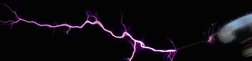
A Tesla coil is a high frequency resonant transformer that generates large plasma arcs.
...like that!
Tesla coils work by first converting the standard 120V of a household wall outlet (at least in our case) to 20-40 thousand volts. The current then charges a bank of capacitors; when the capacitors reach the desired capacitance, the stored charge jumps the spark gap and allows current to flow into the primary coil. This happens many times per second (well within the RF range of 3 kHz to 300 GHz), causing the primary circuit to oscillate. The primary coil then generates an electromagnetic pulse. As the pulse travels up the secondary coil (a coil of 22-24 gauge copper magnet wire wrapped around a hollow plastic tube) it induces a high voltage current as explained by Faraday’s Law (Any change in the magnetic environment of a coil of wire will cause a voltage to be 'induced' in the coil) that then passes into the topload, usually a sphere or toroid made of aluminum. There is some energy loss in the energy transfer between the two coils, however, most energy is transferred from the primary coil to the secondary coil. As the energy of the secondary coil builds, the amplitude of the toroid's voltage rapidly increases and the air around the toroid begins to experience dielectric breakdown (the formation of electrically conducting regions in an insulating material exposed to a strong electric field), forming a corona discharge (a discharge caused by the ionization of a substance surrounding a conductor). The topload then discharges the excess charge into the air. When the electrical charge on the toroid is discharged into the surrounding air, electrical energy is transferred to the air, producing light, sound, and heat.
In a normal transformer the increase in voltage is determined by the proportion of secondary coils to primary coils. For example, 10 coils in the primary coil and 1000 coils in the secondary coil will cause the voltage to increase by 100 times. However, due to the resonance in a Tesla coil, it is possible for much higher voltages to be reached. As the secondary coil's energy and output voltage continue to increase, larger pulses of current ionize and heat the air at the point of initial dielectric breakdown. This forms a conductive column of plasma, called a leader, that extends outward from the toroid. The plasma within the leader is considerably hotter than the corona discharge, and is much more conductive. The leader then branches into thousands of shorter, thinner discharges called streamers that project in all directions. The streamers appear as a blue haze at the ends of the brighter leaders. In a spark gap Tesla coil, the transfers of energy between the primary and secondary coils happens repetitively at typical pulsing rates of 50–500 kHz, so previously formed leader channels are unable to fully cool back to normal temperature between pulses. As a result of the plasma retaining some heat from the initial pulses, new discharges can build upon the pathways left by their predecessors and the size and length of the leader increases with each discharge. The discharges grow until the energy available from the Tesla coil during each pulse balances the energy lost in the discharges through heat, sound and light. At this point, dynamic equilibrium is reached, and the discharges reach their maximum possible length. High-voltage discharges create filamentary multi-branched discharges which are bluish purple in color. High-energy discharges create thicker discharges with fewer branches that are pale and very bright. The important factors for maximum discharge length are thought to be voltage, energy, air movement, barometric pressure and humidity. More than 100 years after the invention of the Tesla coil, many aspects of Tesla coils remain unknown. The energy transfer process and the discharges are still not fully understood today.
After some background investigation, a unique plan for construction was formulated. This design implemented different components from different sets of plans that were found online and in books. A set of calculations was performed whose equations were also found through research. These calculations were used to determine the specifications for different components - see table below.
Component Parameters
| Power Supply | |
| NST Input Voltage | 120 V |
| NST Input Frequency | 60 Hz |
| NST Output Voltage | 9000 V |
| NST Output Current | 60 mA |
| NST VA | 540 VA |
| NST Impedance | 150000 Ω |
| NST Watts | 554 Watts |
| Primary Capacitor | |
| Primary Resonant Capacitance | 17.7 nF |
| Primary Capacitance | 16.7 nF |
| Secondary Coil | |
| Secondary Form Diameter | 3.5 in |
| Secondary Wire Winding Height | 19.4375 in |
| Magnet Wire AWG | 24 AWG |
| Secondary Coil Turns | 857 turns |
| Secondary Capacitance | 7.4 pF |
| Secondary Height-Width Ratio | 5.6 : 1 |
| Secondary Coil Wire Length | 785 ft |
| Secondary Inductance | 10.7 mH |
| Toroid | |
| Major Diameter | 10 in |
| Minor Diameter | 3 in |
| Toroid Capacitance | 11.1 pF |
| Primary Coil | |
| Required Primary Inductance | 11.9 μH |
| Tapped at | 6.6 turns |
| Resonant Frequency | 358 kHz |
Construction
A unique construction plan was formulated and followed. The design incorporated several features from a collection of different designs that were found in research. Building began after all necessary planning was carried out.
Base
For the construction of the base, a large piece of 2 cm ply-wood was cut into two circles approximately 0.7 m in diameter that were connected with 3 pieces of 0.4 m of ¾ inch inner diameter PVC that were attached using 6 PVC flanges. Three 2-inch locking caster wheels were attached to the bottom board with miscellaneous screws.

Figure 1. Base assembly complete with primary and secondary coils in place
Control Box
The control box was constructed using a plastic project box purchased from Radio Shack® with a steel cover. Inside the project box was an A/C line filter purchased from eBay®. Three 120 VAC neon lamps also purchased from Radio Shack®, one SPST switch and two DPST switches were installed in the box. The wiring was done using 10 m of 120 VAC standard wire recycled from overhead projectors. Two IEC plugs recycled from two Dell® computers were used to make the output connections. Also taken from the computers were two IEC plugs/wires that were used to connect the control box to the Tesla Coil.

Figure 2. Inside the control box. A/C line filter takes up most of the space.

Figure 3. Front face of control box

Figure 4. IEC plugs on side face of the control box that provide power to both circuits in the Tesla coil.
One standard wall outlet was modified and mounted on the base of the Tesla coil to act as the input connection for the Tesla coil. For all of the low voltage wiring on the Tesla coil circuit and the fan circuit, recycled overhead projector wires were used. For high voltage wiring in the Tesla coil circuit, 25 ft of 15 kV high voltage wire was used.
Power Factor Correction (PFC) Capacitors and Terry Filter
Two 50 µF metallized polypropylene motor run capacitors were used as PFC capacitors.

Figure 5. PFC capacitors
A 9 kV 60 mA 60 Hz output neon sign transformer with no GFI was purchased new online. The 12 capacitors, 12 bleeder resistors, 12 metal oxide varistors, and two 100Ω Dale resistors were purchased on eBay®. The capacitors, metal oxide varistors and bleeder resistors were mounted on a 4” by 6.5” PC board purchased from Radio Shack®. Five custom made spun brass 1 inch ¼ inch tap brass balls were purchased from Liberty Brass; three of which were included in the Terry filter design and two of which were used as a safety gap across the MMC bank. 25 porcelain standoff insulators were purchased online and used to mount the safety gap balls, main RF ground connection strip and the input connections. All of the Terry filter components were mounted on a recycled polyethylene cutting board.

Figure 6. Terry filter
Spark Gap
The spark gap assembly was constructed using 0.3 m of 4-inch inner diameter PVC pipe as a housing with two fans recycled from overhead projectors wired in a separate circuit than the Tesla coil with two resistors also taken from overhead projectors. Two copper connections were used to hold two 99.5% pure Tungsten rods which acted as the spark gap, all purchased on eBay®. The spark gap was mounted on 1/8-inch acrylic.

Figure 7. Tungsten electrodes of spark gap mounted inside quenching chamber.

Figure 8. Insulative tape was placed in the inside of the chamber to protect the PVC housing. The spark gap not only produces high temperatures, but also UV light.

Figure 9. Closed spark gap

Figure 10. Two fans working in conjunction with each other provided the necessary quenching for the spark gap
Primary Capacitor (MMC – Multiple Mini Capacitor)
The multiple mini capacitor bank was mounted on 1/18 inch thick 10” by 13” acrylic. Nine 0.15 µF Cornell-Dubilier each rated at 2,000 VDC were wired in series; each capacitor was wired in parallel with a 10 MΩ bleeder resistor.

Figure 11. Layout of MMC

Figure 12. MMC complete with bleeder resistors
Primary Coil
The primary coil was mounted on four pieces of ¾ inch inner diameter PVC converging at a PVC x-connector. 20 feet of ¼ inch copper refrigeration tubing was used as the primary coil. Hot glue and cable ties were used to hold the primary in place.

Figure 13. Primary coil
Secondary Coil
The secondary coil was constructed from a 3 inch inner diameter PVC pipe of 0.6 m length wrapped with 800 feet of 24 AWG enameled copper magnet wire. Double sided tape and acrylic spray coating were used to keep the wire in place.

Figure 14. Secondary sits as acrylic spray dries. When winding, the left side was attached to a drill.
Topload
The topload was constructed using 3-inch diameter aluminum heating duct which was wrapped around two circles of high-density fiberboard spaced with PVC and secured with hot glue. The duct was coated with dry wall filler which was varnished and covered with aluminum tape.

Figure 15. Covering the heating duct with dry wall filler

Figure 16. Toroid sits as dry wall filler dries

Figure 17. Vanish applied and toroid sits to dry

Figure 18. Completed toroid covered in aluminum tape. Much cheaper than a custom turned toroid!
The topload was connected to the secondary using a 3-inch PVC end cap and a ¼ inch diameter nylon bolt and nut.

Figure 19. Secondary-toroid connection wire.
A 1 meter ½ inch copper tube was used as the RF grounding rod. All of the wire connections were done using fine rosin core solder and miscellaneous ring terminals and tab terminals. Miscellaneous screws, bolts, nuts, cable ties, right angle joints and wood scraps along with hot glue were used to fasten all components to the base.
Some Results!
After construction was completed and the Tesla coil was tested with positive end results. The longest measured arc was 0.61 m which exceeded initial expectations. After initial problems in testing including racing arcs along the secondary and malfunctioning components, several adjustments were made to the design that eliminated such problems.

Figure 20. The Tesla coil with a light bulb on the toroid.

Figure 21. A long exposure shot of the Tesla coil.