
HOME / POSTS / HERRESHOFF STEAM ENGINE
Herreshoff Steam Engine
September 2017 Bianchini
Project Documents
For my undergraduate thesis, I documented my process in manufacturing sand cast parts for a 1897 Herreshoff steam engine. The project got started through the Pappalardo Apprenticeship program I had joined the previous year. The final functional steam engine is part of a demonstration at an MIT Museum exhibit on Nathanael Greene Herreshoff that opened in fall 2018. I manufactured four of the engine components: the iron column, two iron gibs, and the bronze bearing crosshead.
The thesis is published to DSpace@MIT at this URL.
Pappalardo apprenticeship
I was able to work on this steam engine project through a Pappalardo apprenticeship. Linked to the mechanical engineering robotics course 2.007 Design and Manufacturing, Pappalardo apprentices spend half of their time mentoring students in 2.007 and the other half further developing their own design and manufacturing experience. Seniors in spring 2017 and 2018 collaborated on this steam engine recreation for the purpose of being a part of a Nathanael Greene Herreshoff exhibit at the MIT Museum. I started early in my fall 2017 semester, and I used this head start as material for my thesis.
Architecture of the recirculating steam engine
The recirculating steam engine is a double-acting steam engine. A double-acting steam engine is one whose valve allows the highpressure steam to act on both the up and down strokes of the piston. The entire system converts heat energy into mechanical work, beginning with heat in the form of steam and providing rotational energy of the crankshaft.

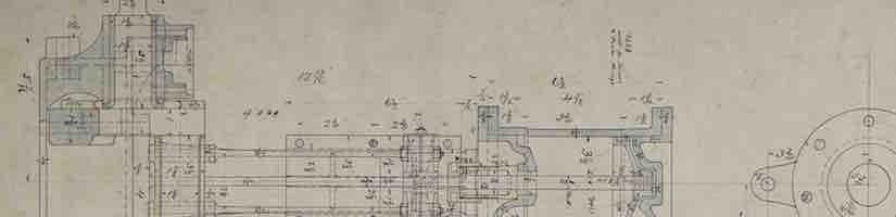
The original Herreshoff assembly drawing. The valve cylinder is on the right, and the power cylinder is on the left. The crankshaft is shown in profile at the bottom in the bed plate.

An "exploded view" of the Pappalardo apprentices' physical progress in April 2018. I made the column and bearing crosshead (labeled) as well as the gibs (on either side of the column).
Sand casting process
To sand cast an object, first the part design must be changed to better suit the sand casting process. This redesign depends on what is called the pattern design. The first physical step is to fabricate patterns, around which sand is packed and then the patterns removed to form the desired cavity shape. Because the patterns have to be removed from the sand before pouring the molten metal, their design has to be done carefully, including eliminating overhangs, incorporating generous drafts, adding thickness to surfaces that require a machine finish, and scaling by a factor that will compensate for the metal shrinkage as it cools to room temperature. Typically this means making multiple pieces for one pattern, and occasionally cores made out of resin sand are required to create interior geometries. I made each of the patterns out of rigid polyurethane foam on a CNC Prototrak mill, using HSMWorks as my CAM software.
After making the patterns, the sand casting flasks should be packed with sand around those molds. Next is the gating and risering strategy, which involves how the molten metal gets poured into the mold cavity. The outcome of the sand casting is highly dependent on this strategy, and there is no exact science. Thus, this was a cool learning process and required iterations.
When the sand cast part is poured, the last step is post-machining. This step means cutting off the gates, establishing datum surfaces, and machining any faces or features that need to be to a finished dimension.
Now that I've given a brief background of the sand casting process, I'll go into detail for each of the parts I made.
Column
Design
The column serves the purpose of holding up the cylinders (in combination with the stanchion) from the bed plate, as well as providing a smooth surface on which the bearing crosshead can slide.

The original Herreshoff column drawing. The gib pieces are also included in this drawing. Note the H cross-section shown in the bottom left.
Patterns
The final patterns I made did not exactly match the part as drawn in the column Herreshoff drawing. That drawing above, dated June 9, 1897, specified an H cross-section throughout the entirety of the column height. However, the assembly drawing, dated June 17, 1897 as shown a couple pictures up, instead showed a column with just a T cross-section below the bearing surface. Since this assembly drawing was dated 8 days later than the column drawing, the more recent drawing was ultimately used to create the most accurate part for the assembly. By this point, two versions of patterns had been made, and a flask was packed using one of them. With this new realization, the third and final version of the CAD model and patterns were made to better suit the assembly drawing version of the column. All three patterns fabricated are shown below, with the top pattern made as drawn in the column drawing and the bottom pattern made as drawn in the assembly drawing.

I made three versions of sand casting patterns for the column piece. The top one matches the column drawing; the bottom matches the engine assembly drawing; and the middle one was an attempted redesign to alleviate some sand packing issues before I arrived at the bottom design.

The four operation toolpaths to turn a block of foam into a pattern half. All the CAM was done in HSMWorks built into SolidWorks.
I chased the end mill doing its work while the mill ran the CNC program I made in HSMWorks.
Packing the mold
Packing the flask with sand involves a hand rammer and a lot of effort. Depending on the size of the flask, this process can take several hours (and can leave you sore...).

My friend, Yasmin, looked shockingly happy in this picture compared to how much she said she liked packing the flasks. Note the ramming tool in her hand.

After packing the sand around the patterns, I opened the flask along its split plane to get ready to remove the patterns. Note that there are pins to align the pattern halves while the sand was packed.
After removing the patterns, the sprue, well, runners, gates, risers, and vents can be added. I made these with spoons and copper tubes.

After removing the patterns, I made the sprue (the hole in the upper left corner), the well (the pocket in the upper right), runners, gates, and risers (the two small holes at either end of the part in the left flask).
Pouring the iron
Pay attention to the two extra spots of molten iron that pop out the top of the flask: those are the tops of the open risers, and they give feedback that the mold is full.
The column piece was specified as cast iron. Iron has a somewhat unique property, in the same way as water, in that it expands when it freezes. For sand casting, this is hugely desirable because that means the freezing part doesn't have to draw more molten metal from risers. Likely because of this attractive property, the first cast came out perfectly!
"Breaking out" a cast part can take a good bit of effort, as the sand is tightly packed and can even get a bit harder due parts of it baking when the metal is poured.
Post-machining to complete the column
Several features from the drawing were eliminated in the castable version: 3 flat machined planes and 10 holes. As with any cast piece, the column began with no trustworthy surfaces: i.e. no perfectly flat, round, or dimensioned features. This leads to some challenges involving proper orientation of the part as well as fixturing.
Proper orientation of the part is critical, especially for long parts such as the column, as a mere 1 degree offset of the part results in a height difference of 0.017” per inch of length. This means that a 1 degree offset of the column would result in a 0.221” height difference between the top and bottom flanges of the part. Thus, thorough orientation of the part is necessary. Typically this is done using a level and averaging the level readings over a large surface of the part. Fixturing is additionally a critical aspect of the postmachining process, particularly when establishing the first datum surfaces. It is important to not treat any surfaces as perfectly flat, and to instead clamp at many small contact points. Additionally, any cantilevered features could vibrate during machining, resulting in poor surface finishes.


A series of independently adjustable fingers and individual support points fixtured the raw cast iron part. There were 7 of these clamping points in total. To begin establishing datum surfaces on the column, first the sides of the bearing surface were squared to use as a clamping surface for further machining. These planes were none of the 3 flat machined planes required to finish the part, though it allowed more robust clamping method for further operations.


I made custom vise jaws to be able to grip the sides of the column while clearing the rib features on the underside.
Using a shell mill to face the bearing surface of the column.


These show the results of facing the bearing surface, then I added the six bolt holes for the gibs.


The final machining steps for the column were to face the upper and lower mounting surfaces and to add two bolt holes on each.
Bearing Crosshead
Design
The bearing crosshead is the linkage that helps convert linear cyclic motion of the piston to rotary motion of the crankshaft. T he power connecting rods interface with the bearing crosshead, free to rotate about the cylindrical arms. The dovetail feature on the other side of the bearing crosshead slides along the column and is constrained to only vertical linear motion by the column and gibs. A rod threads into the bearing crosshead, extends vertically, and transfers the matching vertical linear motion to the power piston.

The bearing crosshead drawing is just a part of a subassembly drawing. The bearing crosshead can be seen in the top row and the upper left corner of the lower left subassembly.
Patterns
I made the part using two cores, each to fill the cone-shaped void in the ends of the cylindrical feature. The parting plane thus split both the cylindrical feature and the dovetail feature in half along a plane of symmetry. The pattern halves were identical, as were the two cores. In addition to these pattern halves, I also made in a similar way coreboxes, into which resin sand is packed and cured to make the cores.

To make a part with cores, I needed to add coreprints into the pattern. To locate a core in the correct position within the mold cavity, coreprints are extra bosses included on patterns that result in extra voids in the mold cavity. These extra voids provide space for cores to be supported and located properly in reference to the rest of the mold cavity.


From left to right: CAD of one half of the corebox, and the four resulting core halves (note that there are two cores in the part).
A lesson in alloys and castability
Parts on the Herreshoff drawings are labeled as “bronze,” “iron,” or “steel,” with no specifications for what type of each. Given that there are numerous kinds of copper alloys and their properties, we selected a copper alloy that would best suit the use case of the bearing crosshead: a load-bearing piece with low friction sliding/rotating features. We initially chose copper alloy C95400, an aluminum bronze, for its high strength and excellent bearing properties.
In total, three bearing crosshead pieces were attempted in aluminum bronze, each with increasingly generous risering strategies. Repours were necessary because each iteration saw significant shrinkage defects. A “generous” risering strategy is one that provides extensive risering with efforts to keep these risers hot and full of molten metal, mostly by using insulated tubes or by including hot risers which do not touch the outside air. The second attempt used one insulated riser, though the resulting part still showed shrinkage defects in the center of the knuckle. The third attempt featured a cold insulated riser tube on top of the part itself, on the short cylindrical boss below which we saw the most extreme shrinkage defects. Despite the drastic differences in risering strategies, all three of the resulting cast parts exhibited extreme shrinkage defects, always in the middle of the cylindrical piece and additionally elsewhere for some.


Cross-sections of these failed attempts illustrate the extreme shrinkage in the center of the part as well as near the base of the bearing surface.
I ended up switching the alloy altogether. Some research I did into copper alloy properties reflected the difficulties I faced in casting with aluminum bronze. I changed to a red leaded brass C83600, and the resulting casting worked on the first try.
|
CDA # |
Family |
Shrinkage Allowance (%) |
Melting Point (oC) |
Castability Rating |
|
836 |
Leaded Red Brass |
5.7 |
1010 |
2 |
|
844, 848 |
Leaded Semi-Red Brass |
1.4-2.0 |
970 |
2 |
|
854 |
Leaded Yellow Brass |
1.5-1.8 |
940 |
4 |
|
858 |
Yellow Brass |
2.0 |
925 |
4 |
|
863, 865 |
Manganese Bronze |
2.3 |
920 |
4, 5 |
|
872 |
Silicon Bronze |
1.8-2.0 |
... |
5 |
|
875 |
Silicon Brass |
1.9 |
915 |
4 |
|
903 |
Tin Bronze |
1.5-1.8 |
980 |
3 |
|
922 |
Leaded Tin Bronze |
1.5 |
990 |
3 |
|
937, 943 |
High-Lead Tin Bronze |
1.5-2.0 |
930 |
2, 6 |
|
953, 958 |
Aluminum Bronze |
1.6 |
1055 |
8 |
|
976, 978 |
Nickel Silver |
1.6-2.0 |
1165 |
8 |
Table 1: Foundry properties of the principal copper alloys used for sand casting. The castability rating is a scale from 1 to 8, where 1 is the ideal casting material, and 8 is the least ideal casting material. Note in the highlighted rows that my original aluminum bronze alloy was rated the least castable rating, while my second red leaded brass is rated as a very favorable casting material. Information from Metals Handbook published by the American Society for metals, a book I highly recommend for anyone who wants to learn more about casting.

Finally, the successful bearing crosshead casting, in red leaded brass! Notice the extensive risering system: two large risers at either end of the cylindrical feature, with a large sprue gating in two places into the bearing surface.
Post-machining to complete the bearing crosshead
I had to eliminate several features from the drawing in the castable version that I now needed to machine back into the cast part: several flat machined planes, 2 cylindrical features, and 2 holes. To begin establishing datum surfaces on the bearing crosshead, the regular mill vise clamped the part by the knuckle, orienting the flat bearing surface upwards. A level ensured sufficient orientation of the part. To decrease vibrations while cutting, I tapped wood wedges to support the cantilevered arms.

I always draw a parts I machine neatly in a notebook so I can use it as a reference as I am machining. Here is the drawing I made for the bearing crosshead.


I started post-machining the bearing crosshead by facing the bearing surface (left) and squaring its four edges (right).


I made use of my squared edges done in the step above in order to take down the sides and ends of the knuckle (right). I located the approximate center of the part using a fish tail (left and middle).


I used a circular interpolation event on the mill to bring one side of the knuckle's cylindrical boss to size (left). I then used a long ball end mill to put a fillet at the bottom of the boss (middle). You can see the difference between the finished and unfinished sides of the knuckle (right).


To ensure the second side of the cylindrical knuckle was perfectly colinear with the other side, I fixtured the finished end in a collet block, which allowed me to accurately locate the center of the first side (left). I then drilled and tapped a hole in the center of the part (right).

There was a fillet called out to be finished on the original drawing right by the rib connecting the knuckle and bearing surface. I made this fillet with a ball end mill.


I tilted the head of the mill to the angle that matched the gibs (which I had finished after the column piece) so that I could finish the slanted dovetail surface (left, with the gib on top to show matched angles). The finished dovetail half contrasts with the naturally rough surface of the sand cast part (right).
To ensure proper sliding clearances for the bearing crosshead inside the gibs and column assembly, I used gauge pins of the same diameter as the thickness of the bearing crosshead rib as I tightened the gibs to the column.

After some adjustments to fit the four pieces together with a low-friction sliding fit, I had completed this sub-assembly of the engine!
The full steam engine
Video of running the completed engine with compressed air.

The full engine assembly. After a nice paint job, the engine went on display in the Herreshoff exhibit at the MIT Museum beginning in the fall of 2018.
Bonus material! Casting the bed plate, the largest piece in the engine, required building a custom flask and shank for holding the crucible, and required us to use the hydraulic tilting feature of the induction furnace. This video shows that casting! It was the second attempt, and successful.